Wednesday, November 14, 2012

Overview: Sensors

A rover without some means of detecting its surrounding environment is just stumbling around blindly and asking for trouble.

From the outset, the roverbot was intended to navigate autonomously between waypoints, so a GPS receiver is a must.  GPS modules have decreased in price and increased immensely in capability and availability in the last few years.  A modern module can determine its location to within just a couple of meters, and update its position several times per second, making navigation much more accurate than before.

The rover will be driving around outside in relatively unstructured environments, so some sort of obstacle detection and avoidance will also be required.  I plan to use at least a couple of sonar units for obstacle detection and ranging, and I also have a pair of IR distance sensors in-hand.  I'm not sure just how useful the IR distance sensors will be in an outdoor environment, where they may get swamped by sunlight, but I'll give it a shot and see how/if they work.

It would be nice to have some idea of what's going on with the drive system too, so I plan to attach temperature sensors to the motor and speed controller.  I've got a fan mounted to the heat sink of the motor's speed control, so I'll be able to turn on a bit of cooling when the temperature starts to rise.

Finally, I have an accelerometer breakout board that I won in the trivia question segment of Adafruit Industries' Ask An Engineer webcast a while back.  I plan to build this into the rover, to give some indication of tilt, perhaps to implement some sort of rollover avoidance, since all of the electronics is probably going to end up making it somewhat top-heavy.

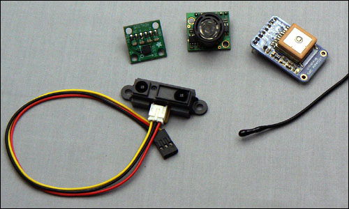
An assortment of sensors
Top row: Accelerometer, sonar, and GPS
Bottom row: IR distance, and thermistor

In robotics, a bumper switch is a sensor whose primary function is to inform you that the rest of your sensors are not up to the task of navigating in a particular environment.  In other words, if an obstacle makes it to the point of triggering the bumper without being detected by any other sensor, you have a hole in your detection array which should probably be fixed.  The Creeper's rock-crawler chassis poses a little bit of a challenge for mounting a bumper.  The whole point of the design is to put the wheels on the far corners for being able to climb and mount obstacles, and keep everything else as far up and out of the way as possible; a bumper would just interfere with the ability to deal with the extreme terrain that it's designed to be driven on, so other than a basic skid plate over the differential, no protection along those lines is provided.  Regardless, I'm sure I'll be able to work something out with a little bit of tweaking.

That's about it for the preliminary overview of the rover's component parts.  The next post will be about the actual build-up of the chassis, with some notes about the Creeper kit, and a couple of very minor modifications to adapt it for use as a robot chassis.

Tuesday, October 30, 2012

Overview: Feedback and Telemetry

It's one thing to have a rover that you can drive around (or which drives itself around) within your line of sight where you can see what it's doing, but to really get a feel for what's going on, or to expand beyond the immediate area, you need a way to get some information from the rover back to the control point.

For this project, I will be using an amateur television link to provide video feedback from the rover's point of view, as well as telemetry data overlaid on top of the image.  The small video transmitter I have available should be sufficient to send a signal a good distance away, and has an audio channel available, which I might use for sending packetized data as well.

The Videolynx Z70A ATV transmitter


The Videolynx Z70A has an output of 50 to 100 mW on the 70cm (440 MHz) ham band.  Using this band simplifies reception quite a bit, since the image can be received by any television with an analog CATV (cable TV) tuner built in.  This band is also quite removed from the frequencies that the control system will be using for communications, so there will hopefully be no problems with crosstalk or swamping.

The BOB-4 video overlay unit, on a carrier board

For video overlay, I will be using a BOB-4 Video OSD module from Decade Engineering.  This is a very capable module which, while a bit larger than some on-screen display units, allows for the use of halftone video and graphic elements.  It is available in both SIMM and 0.10" header form-factors, depending on your particular application.  As you can see in the photo above, I purchased the SIMM version before deciding that what I really needed was a header-based connection.  Some creative soldering did the trick though, and it now occupies less space than before, while retaining all of its functionality.

An assortment of small video cameras from the parts bin

For capturing the video in the first place, I have a number of small video cameras available.  I'll be using a micro camera of one type or another, in the interest of keeping it light and mobile.  Many smaller inexpensive cameras have lower resolution, but I figure I can start out simple and work my way up to better units as things progress.

In the next installment, I'll briefly discuss some of the sensors I'll be using onboard the rover, and then it will be on to the actual building process!

Friday, October 19, 2012

Overview: Onboard Logic

From the outset, the roverbot project was planned to be more than just an elaborate radio-controlled car.  The plan is for it to be able to navigate autonomously between GPS waypoints while detecting, avoiding, and navigating around obstacles in its path.  To do so, it will need some amount of onboard logic to do the "heavy lifting" tasks involved in performing that navigation.

To that end, the roverbot carries an Arduino Mega 2560 microcontroller board, interfaced to a variety of sensors and modules.  At the heart of the Mega board is an Atmel ATMega 2560 processor, with 256 KB of flash memory for storing program code, 8 KB of SRAM, and 4 KB of non-volatile EEPROM storage space.  It runs at a clock speed of 16 MHz, and features 54 general-purpose I/O lines, 16 analog input lines, and 4 dedicated hardware serial ports.  This may not sound like much as compared to the computer you're reading this on, but it's not too shabby, either.  In addition, the Arduino line has a huge user support base, with tons of resources and libraries available.

Arduino Mega 2560 (Photo from Arduino website)

Since I started the roverbot project, there has been a very interesting development in the world of embedded computing: the Raspberry Pi.  This is a small single-board computer, selling for approximately $35, which comprises a complete Linux system.  Created for teaching programming in schools, it's got a great feature set and is catching on like wildfire.  It features some general-purpose I/O lines, although not nearly as many as the Arduino Mega does, and they're only digital I/O, without support for reading analog values directly.  All of this can be worked around however, and there are a good number of interface boards available to enhance the capabilities of the Pi.

Raspberry Pi (Photo from Wikipedia article)

At the moment, the Arduino Mega board is more than powerful enough for what I'm asking it to do.  With a retail price between that of an Arduino Uno and an Arduino Mega 2560, the Raspberry Pi is powerful and affordable.  Probably the biggest barrier keeping me from switching the roverbot's brains to a Pi is that I am not (yet) fluent in Linux or Python.  For simplicity's sake, I'm sticking with the Arduino for the time being, but the Raspberry Pi is certainly an attractive option, which I may have to look into at a later date.

Next up, I'll take a look at some of the sensors I'll be using on the roverbot.

Overview: Command and Control

Oh boy, has this gone through some changes since my first post!

Initially, I had planned to implement a control system using packetized data transmitted via amateur radio frequencies.  While it is possible to pull off such an arrangement, I have come to realize that it isn't entirely practical for a rover of this type and size.

Point-to-point data transmission on the ham frequencies is usually accomplished through the AX.25 "packet radio" protocol, with a data rate of 1200 or 9600 bps, on frequencies of 144 MHz and up.  These transmission speeds, combined with the size, weight, and power requirements of the radios involved make this a less-than-ideal solution for this project.

Once I decided against the packet radio solution, I spent a bit of time working out a system that used a couple of Arduino microcontroller boards connected via XBee wireless modules.  I did in fact manage to get a basic control system cobbled together, but it was far from ideal.  It was relatively slow, had fairly high processor requirements, took a lot of tweaking to get the timing right between the transmitter and receiver, and didn't cope well if you weren't constantly checking and reading the Arduino's serial receive buffer.  It also had an unfortunate tendency to develop transient glitches after it had been running for a while.  It didn't really take too long to figure out that this wasn't going to work.  The XBee modules also apparently have some provision for directly transmitting analog values, but I didn't examine that option too closely because...

I finally got smart, stopped re-inventing the wheel, and took a look at what other rover and drone builders were doing to handle the control functions.

To make a long story shorter, I ended up settling on using a 5-channel radio designed for aircraft use, transmitting on the 2.4 GHz band.  Older analog R/C radio sets were very specific about which frequency sets were to be used for which type of models (ground or air operation); modern 2.4 GHz digital radios are far more adaptable and less prone to interference, so it no longer matters what you use a given radio for.  As with the mobility base, the off-the-shelf solution is proving to be a far more viable solution, which is easier to use and has better performance overall.  Just the robustness of the link and ease of implementation make it a winner.

I will still be using amateur radio on the rover - the onboard video downlink will use the 440 MHz ATV frequencies, and I will probably be sending some telemetry back wrapped up in AX.25 packets as well.  The XBee modules will also find a use, providing a reliable data channel for control signals that won't be sent via the R/C transmitter.  This will still see a good bit of use, since the goal of the roverbot is for it to primarily be an autonomous rover, with manual drive being just one relatively minor mode of operation.

In the next post, I'll talk a little bit about the onboard logic, the way it's configured now, and where it might be going as things get more complex.

Overview: Mobility


In this post, I will talk briefly about the basic mobility base that the roverbot will be built around.

The roverbot will be based on a commercially-available radio-controlled vehicle chassis.  While it may not have the "geek appeal" of designing a mobility base from scratch, this approach will have the advantage of using a known-good platform to start with, which will allow me to concentrate on control, navigation, and other systems, instead of spending all of my time hammering out little physical details.  I have nothing against scratch-building a base - my initial plan was to start with a three-wheel differentially-driven tail-dragger design, eventually migrating to a custom-built treaded design using some really nice track units from Lynxmotion.  Unfortunately, right now I just don't have access to the tools or building space that I would need to do it properly.  I would rather defer it until a later project and do it right than to do a half-baked job using what I have available right now.

In addition, I have already had a bit of experience in working with radio-controlled vehicles.  I used to race R/C trucks some years ago, and so am at least somewhat familiar with the mechanics of getting them to do what I want.  Not surprisingly, things in the hobby have changed considerably in the years since I dropped out of racing, but the fundamentals are still the same.  There will no doubt be a learning curve involved, but it shouldn't be too rough.  After a good deal of poking around and re-learning a few things, I sat down to assess what features I was looking for in a robot base, and compare them to what was available on the market.

In the end, I went with a rock-crawler model from Venom Racing (now apparently Atomik), called the Creeper.  

Venom (Atomik) Creeper (photo source: Atomik website)

It features high-articulation suspension for terrain handling, along with provision for adding rear-wheel steering, and a single, centrally-mounted motor (as opposed to two motors, mounted on each axle, as some models use).  Many rock-crawler models have permanently locked differentials on the ends - essentially just solid axles in a differential-shaped housing - to eliminate wheel spin.  The Creeper features working diffs that can be locked manually.  Since I'm actually interested in having the differential action in the roverbot, I'll be leaving mine active.

The ability to upgrade to four-wheel steering was another plus.  I may have given up the zero turning radius of a tracked base, but the ability to steer sharply with both ends of the rover should help to keep the turning radius tight enough for a reasonable amount of maneuverability.

Finally, there's the suspension.  The extreme deflection of the rock crawler chassis may be a bit of overkill, but whether driven manually via a video link or running in autonomous navigation mode, it is certain to run up against a good number of obstacles that will simply be missed by the control system, so the ability to handle large bumps and obstacles will surely come in handy.

There are some definite quirks to the Creeper chassis design, which I will cover in more depth in a later post, but for the most part, it seems to be a pretty capable chassis which will serve well for this project.

My next post will take a look at the wireless link from the control station to the roverbot.  Of all of the rover's subsystems, the control link has gone through the most changes so far.  More on that next time.

Getting Rolling.....Again.

Well, I guess it's been a while, hasn't it?

A lot has happened since that original post.  Unfortunately, most of it didn't involve the roverbot project.  I had a few things come up which prevented me from doing any work at all on any of my various projects.  After a few false starts however, I'm finally making a bit of progress.

The Plan:
I had originally intended to document the entire build extensively as progress was made, but my current workspace places quite a few limits on that sort of thing.  For the most part, I can be set up for building or taking halfway-decent documentation photos, but not both at the same time.  I'll be sharing what I can, as well as I can, though.

As before, the plan is still to work my way up incrementally from a basic mobility platform, incorporating systems and increasing complexity as I go.  The next few posts will include some more specific information about the various components that will make up the basic systems of the roverbot, along with a bit of discussion about why each piece was chosen, and where I plan to go with it.  After that, I'll be getting into the actual building and integration of the various systems, and start working towards an actual roverbot.

I have to admit that my efforts at documentation have progressed somewhat slower than the actual build, and the roverbot has outpaced my blog entries somewhat (largely because I keep meaning to get some good photos and illustrations before posting - see above regarding the workspace).  As a result, some of the upcoming entries will be a little bit time-compressed, and the times between the blog posts will not accurately reflect the time between the progress shown in them.  It should all get caught up before long though, and I'll eventually be posting in real-time as I develop things.  There will no doubt be some dead-ends and blind alleys along the way, and I welcome questions and feedback on anything.  It should be fun.

Thanks for reading!

Tuesday, May 31, 2011

Getting Rolling

Hello there!

Welcome to Project Rover - a blog where I will be posting updates about the progress I make in the design and construction of a rover robot. As I am sort of working as I go, I will be taking the build in small steps, building systems on top of systems in increasing complexity.

I will be starting with a basic mobility platform and working my way up to a more complex base, capable of handling some terrain. Similarly, the control system will begin as a basic remote control setup using simple commands to drive it manually, but I hope to quickly progress to more advanced methods, to eventually include GPS-based autonomous navigation and adaptive terrain-sensing guidance.

I am a licensed amateur radio operator, and as part of the design, I hope to utilize ham radio for control, feedback, and telemetry on the rover. Planned systems include packetized data for command and control functions, and low-power amateur television and APRS for video backhaul and telemetry.

Although this blog is largely for my own records and to provide a space for my own notes and observations, I hope that I can make it interesting for anyone interested in robotics, radio, electronics, or just neat technological stuff. This project has actually been in the works for quite some time now, and I'm excited to finally be making some progress on it. I hope that you will find it as interesting as I do, and I welcome your questions and feedback.

Thanks for reading!